Connessione RS-485 tra due PIC
Ciao a tutti, qualche mese fa in una discussione su come rilevare temperature a distanza mi è stato consigliato di utilizzare un connessione seriale RS-485 tra due PIC.
Il primo PIC "master" invia dei byte, il secondo "slave" una volta interrogato, risponde con i dati che ha rilevato.
Ora vorrei provare a realizzare questa connessione, boiler mi aveva consigliato di procurarmi due LTC1487 e di provare in tanto con una connessione RS-233, cosi ho fatto.
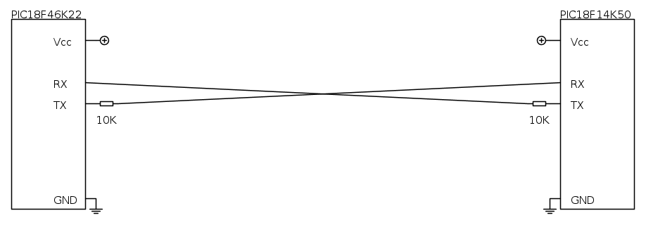
Prova connessione RS-233:
Codice del PIC18F46K22 "master"
Codice del PIC18F14K50 "slave"
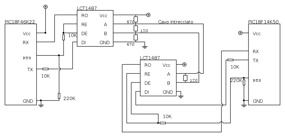
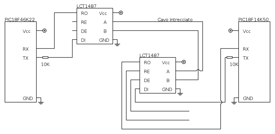
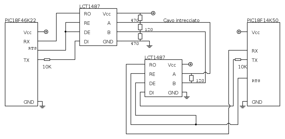
....e questo funziona ora dovrei provare a realizzare la connesione RS-485 collegando i ltc1487 ai miei PIC, ma ho qualche dubbio,
io ho provato qualcosa del genere ma non ho ben capito a cosa vadano collegati RE e DE.
Qui c'è il datasheet http://pdf1.alldatasheet.com/datasheet-pdf/view/70737/LINER/LTC1487.html
ciao a tutti Ivo
Il primo PIC "master" invia dei byte, il secondo "slave" una volta interrogato, risponde con i dati che ha rilevato.
Ora vorrei provare a realizzare questa connessione,
Prova connessione RS-233:
Codice del PIC18F46K22 "master"
- Codice: Seleziona tutto
#define LED1 LATBbits.LATB7
#define LED2 LATBbits.LATB6
#define PULSANTE1 PORTDbits.RD2

void ConfigureOscillator(void);
void ConfigurePort(void);
void ConfigureUSART(void);
void ConfigureInterrupts(void);

char unsigned contatore;
char unsigned pulsante;
char unsigned ch_usart_in[8];
char unsigned ch_usart_num;

void ConfigureOscillator(void)
{

    OSCCON = 0b01110000;    // bit7: device enters SLEEP on sleep instruction[0]
                            // bit6-4: HFINTOSC 16MHz [111]
                            // bit3: status bit [0]
                            // bit2: status bit [0]
                            // bit1-0: clock defined by CONFIG bits [00]
    OSCTUNE = 0b11000000;   // bit7:  device clock derived from the MFINTOSC or HFINTOSC source
                            // bit6: PLL enabled [1]
                            // bit5-0: oscillator tuning [000000]
Delay10KTCYx(10);
}

void ConfigurePort(void)
{
    ADCON0bits.ADON = 0;    //disattivo analogico

    LATB = 0x00;            //Porte B
    TRISBbits.TRISB7 = 0;   //LED1
    TRISBbits.TRISB6 = 0;   //LED2
    TRISBbits.TRISB5 = 1;   //PULSANTE1
    TRISBbits.TRISB4 = 1;   //
    TRISBbits.TRISB3 = 1;   //
    TRISBbits.TRISB2 = 1;   //
    TRISBbits.TRISB1 = 1;   //
    TRISBbits.TRISB0 = 1;   //

    LATC = 0x00;            //Porte C
    TRISCbits.TRISC7 = 1;   //USART
    TRISCbits.TRISC6 = 1;   //USART
    ANSELCbits.ANSC7 = 0;   //0 = Digital input buffer enabled
    ANSELCbits.ANSC6 = 0;   //0 = Digital input buffer enabled

    LATD = 0x00;            //Porte D
    TRISDbits.TRISD7 = 1;   //
    TRISDbits.TRISD6 = 1;   //
    TRISDbits.TRISD5 = 1;   //
    TRISDbits.TRISD4 = 1;   //
    TRISDbits.TRISD3 = 1;   //
    TRISDbits.TRISD2 = 1;   //PULSANTE1
    TRISDbits.TRISD1 = 1;   //
    TRISDbits.TRISD0 = 1;   //

    ANSELDbits.ANSD7 = 0;   //0 = Digital input buffer enabled
    ANSELDbits.ANSD6 = 0;   //0 = Digital input buffer enabled
    ANSELDbits.ANSD5 = 0;   //0 = Digital input buffer enabled
    ANSELDbits.ANSD4 = 0;   //0 = Digital input buffer enabled
    ANSELDbits.ANSD3 = 0;   //0 = Digital input buffer enabled
    ANSELDbits.ANSD2 = 0;   //0 = Digital input buffer enabled
    ANSELDbits.ANSD1 = 0;   //0 = Digital input buffer enabled
    ANSELDbits.ANSD0 = 0;   //0 = Digital input buffer enabled
}

void ConfigureUSART(void)
{
    BAUDCON1bits.BRG16 = 1;
    // 10 417 bps 8 bit + 1 stop
    Open1USART( USART_TX_INT_OFF &
            USART_RX_INT_OFF &      //interrupts su ricezione
            USART_ASYNCH_MODE &
            USART_EIGHT_BIT &
            USART_CONT_RX &
            USART_BRGH_HIGH,
            1535 );
}

void ConfigureInterrupts(void)
{
    RC1IE = 1;
    RC1IP = 1;
    GIE = 1;
    PEIE = 1;
}

void interrupt high_isr(void)
{
    if (RC1IF)
    {
        while (!DataRdy1USART());
        ch_usart_in[ch_usart_num] = Read1USART();

        ch_usart_num++;
        if(ch_usart_in[0] != 0x50 || ch_usart_num > 7) ch_usart_num = 0;

            if (ch_usart_in[0] == 0x50 && ch_usart_in[7] == 0x51)
            {
                ch_usart_in[0] = 0;
                ch_usart_in[7] = 0;
                LED2 = ~LED2;
            }
    RC1IF = 0;
    }
}

/******************************************************************************/
/* Main Program                                                               */
/******************************************************************************/

void main(void)
{
    ConfigureOscillator();
    ConfigurePort();
    int i;
    LED1 =1; LED2 =1;
     for (i=0;i<2000; i++) __delay_ms(1);
    LED1=0; LED2=0;
    ConfigureUSART();
    ConfigureInterrupts();
    while (1)
         {
        if (PULSANTE1 == 0) pulsante = 0;
        if (PULSANTE1 == 1) pulsante = 1;
        if (ch_usart_in[5] == 0) LED1 = 0;
        if (ch_usart_in[5] == 1) LED1 = 1;

             Write1USART(0x46);
             while (Busy1USART());
             Write1USART(contatore);
             while (Busy1USART());
             Write1USART(pulsante);
             while (Busy1USART());
             Write1USART(0x00);
             while (Busy1USART());
             Write1USART(0x64);
             while (Busy1USART());

            contatore++;
            if (contatore > 15) contatore = 0;
             for (i=0;i<1000;i++){
                 __delay_ms(1);
             }
         }
}
Codice del PIC18F14K50 "slave"
- Codice: Seleziona tutto
void ConfigureOscillator(void);
void ConfigurePort(void);
void ConfigureUSART(void);
void ConfigureInterrupts(void);

char unsigned pulsante;
char unsigned contatore;
char unsigned aggiorna_dati;
int i;

char unsigned ch_usart_in[5];
char unsigned ch_usart_out[8];
char unsigned ch_usart_num;

void ConfigureOscillator(void)
{
    // FA PARTIRE IL PLL
    OSCTUNEbits.SPLLEN = 1;
    //STABILIZZAZIONE PLL
    Delay10KTCYx(10);

}

void ConfigurePort(void)
{
    ADCON0bits.ADON = 0;    //disattivo analogico

    LATB = 0x00;            //Porte B
    TRISBbits.TRISB7 = 1;   //USART TX
    TRISBbits.TRISB6 = 1;   //
    TRISBbits.TRISB5 = 1;   //USART RX
    TRISBbits.TRISB4 = 1;   //
    ANSELHbits.ANS11 = 0;   //0 = Digital input buffer enabled
    ANSELHbits.ANS10 = 0;   //0 = Digital input buffer enabled

    LATC = 0x00;            //Porte C
    TRISCbits.TRISC7 = 1;   //
    TRISCbits.TRISC6 = 1;   //
    TRISCbits.TRISC5 = 1;   //
    TRISCbits.TRISC4 = 1;   //
    TRISCbits.TRISC3 = 1;   //
    TRISCbits.TRISC2 = 0;   //LED2
    TRISCbits.TRISC1 = 0;   //LED1
    TRISCbits.TRISC0 = 1;   //PULSANTE1
    ANSELHbits.ANS9 = 0;   //0 = Digital input buffer enabled
    ANSELHbits.ANS8 = 0;   //0 = Digital input buffer enabled
    ANSELbits.ANS7 = 0;   //0 = Digital input buffer enabled
    ANSELbits.ANS6 = 0;   //0 = Digital input buffer enabled
    ANSELbits.ANS5 = 0;   //0 = Digital input buffer enabled
    ANSELbits.ANS4 = 0;   //0 = Digital input buffer enabled

}

void ConfigureUSART(void)
{
    BAUDCONbits.BRG16 = 1;
    // 10417 bps 8 bit + 1 stop
    OpenUSART( USART_TX_INT_OFF &
            USART_RX_INT_OFF &      //interrupts su ricezione
            USART_ASYNCH_MODE &
            USART_EIGHT_BIT &
            USART_CONT_RX &
            USART_BRGH_HIGH,
            1151 );
}

void ConfigureInterrupts(void)
{
    RCIE = 1;
    RCIP = 1;
    GIE = 1;
    PEIE = 1;
}

void interrupt high_isr(void)
{
    if (RC1IF)
    {
        while (!DataRdyUSART());
        ch_usart_in[ch_usart_num] = ReadUSART();

        ch_usart_num++;
        if(ch_usart_in[0] != 0x46 || ch_usart_num > 4) ch_usart_num = 0;

            if (ch_usart_in[0] == 0x46 && ch_usart_in[4] == 0x64)
            {
                LED2 = ~LED2;
                ch_usart_in[0] = 0;
                ch_usart_in[4] = 0;

                    WriteUSART(0x50);
                    while (BusyUSART());
                    WriteUSART(ch_usart_out[1]);
                    while (BusyUSART());
                    WriteUSART(ch_usart_out[2]);
                    while (BusyUSART());
                    WriteUSART(ch_usart_out[3]);
                    while (BusyUSART());
                    WriteUSART(ch_usart_out[4]);
                    while (BusyUSART());
                    WriteUSART(pulsante);
                    while (BusyUSART());
                    WriteUSART(ch_usart_out[6]);
                    while (BusyUSART());
                    WriteUSART(0x51);
                    while (BusyUSART());

                aggiorna_dati = 1;
            }
    RC1IF = 0;
    }
}

/******************************************************************************/
/* Main Program                                                               */
/******************************************************************************/

void main(void)
{
    ConfigureOscillator();
    ConfigurePort();
    LED1=1; LED2=1;
     for (i=0;i<2000; i++) __delay_ms(1);
    LED1=0; LED2=0;
    ch_usart_num = 0;
    ConfigureUSART();
    ConfigureInterrupts();

    while(1)
    {
        //controllo se accendero o spegenre led 1
        if (ch_usart_in[2] == 0) LED1 = 0;
        if (ch_usart_in[2] == 1) LED1 = 1;
        //controllo lo stato del pulsante 1
        if (PULSANTE1 == 0) pulsante = 0;
        if (PULSANTE1 == 1) pulsante = 1;

        if (aggiorna_dati == 1)
        {
            // reset del falg
            aggiorna_dati = 0;
        }
   }
}
....e questo funziona ora dovrei provare a realizzare la connesione RS-485 collegando i ltc1487 ai miei PIC, ma ho qualche dubbio,
io ho provato qualcosa del genere ma non ho ben capito a cosa vadano collegati RE e DE.
Qui c'è il datasheet http://pdf1.alldatasheet.com/datasheet-pdf/view/70737/LINER/LTC1487.html
ciao a tutti Ivo

 scusate x il titolo.