
 Elettrotecnica e non solo (admin)
 Un gatto tra gli elettroni (IsidoroKZ)
 Esperienza e simulazioni (g.schgor)
 Moleskine di un idraulico (RenzoDF)
 Il Blog di ElectroYou (webmaster)
 Idee microcontrollate (TardoFreak)
 PICcoli grandi PICMicro (Paolino)
 Il blog elettrico di carloc (carloc)
 DirtEYblooog (dirtydeeds)
 Di tutto... un po' (jordan20)
 AK47 (lillo)
 Esperienze elettroniche (marco438)
 Telecomunicazioni musicali (clavicordo)
 Automazione ed Elettronica (gustavo)
 Direttive per la sicurezza (ErnestoCappelletti)
 EYnfo dall'Alaska (mir)
 Apriamo il quadro! (attilio)
 H7-25 (asdf)
 Passione Elettrica (massimob)
 Elettroni a spasso (guidob)
 Bloguerra (guerra)
Definizione componenti attivi e passivi
Moderatori: ![]() carloc,
carloc, ![]() g.schgor,
g.schgor, ![]() BrunoValente,
BrunoValente, ![]() IsidoroKZ
IsidoroKZ
19 messaggi
• Pagina 2 di 2 • 1, 2
2
voti
[11] Re: Definizione componenti attivi e passivi
![]() da
da ![]() DarwinNE » 12 apr 2014, 12:32
DarwinNE » 12 apr 2014, 12:32
Non è tanto questione di dialettica. È infatti un problema difficile che ha tenuto occupate per più di trent'anni le migliori menti dedicatesi alla teoria dei circuiti.
Follow me on Mastodon: @davbucci@mastodon.sdf.org
-

 DarwinNE
31,0k 7 11 13 - G.Master EY

- Messaggi: 4420
- Iscritto il: 18 apr 2010, 9:32
- Località: Grenoble - France
0
voti
[12] Re: Definizione componenti attivi e passivi
![]() da
da ![]() core » 12 apr 2014, 16:02
core » 12 apr 2014, 16:02
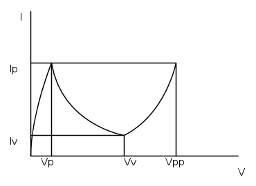
vediamo se ho capito bene questo concetto. Se mi trovo nella zona tunnel sul valore di picco (Vp) all'aumentare della tensione la corrente diminuisce fino al valore di valle (Vv), quindi qui è passivo; mentre se dal valore di Vv torno indietro (quindi la tensione diminuisce) verso il valore di Vp la mia corrente aumenta quindi è in questo caso che lo interpreti come attivo?


0
voti
[13] Re: Definizione componenti attivi e passivi
![]() da
da ![]() core » 12 apr 2014, 16:43
core » 12 apr 2014, 16:43
perdonatemi il disegno non proprio reale:
Ultima modifica di  core il 12 apr 2014, 16:45, modificato 1 volta in totale.
0
voti
[14] Re: Definizione componenti attivi e passivi
![]() da
da ![]() DarwinNE » 12 apr 2014, 16:44
DarwinNE » 12 apr 2014, 16:44
Uh, più o meno... lo sai cos'è un modello di piccolo segnale?
Follow me on Mastodon: @davbucci@mastodon.sdf.org
-
DarwinNE
31,0k 7 11 13 - G.Master EY
- Messaggi: 4420
- Iscritto il: 18 apr 2010, 9:32
- Località: Grenoble - France
0
voti
[15] Re: Definizione componenti attivi e passivi
![]() da
da ![]() core » 12 apr 2014, 22:13
core » 12 apr 2014, 22:13
più o meno.. vuoi dirmi che quando l'elettrone seppur non avendo inizialmente l'energia per superare la barriera, lo troviamo comunque nella banda di conduzione, questo dovuto alla polarizzazione inversa che crea il passaggio dalla banda di valenza a quella di conduzione(fenomeno chiamato rottura zener)?
1
voti
[16] Re: Definizione componenti attivi e passivi
![]() da
da ![]() DarwinNE » 12 apr 2014, 23:13
DarwinNE » 12 apr 2014, 23:13
No, sto parlando dello studio di piccolo segnale.
Qualche tempo fa, in un altro contesto, avevo scritto una breve descrizione di che si tratta, in inglese. La riprendo qui, però non ho il tempo di tradurla ed è forse un po' troppo tecnica.
In analog electronics, one is constantly trying to handle analog signals using circuits which are "as linear as possible". The biggest difficulty of electronics is that almost everything is nonlinear. The most general approach is therefore a time-domain analysis, where the direct application of Kirchhoff laws (along with the most complete models of devices) gives non-linear differential equations. None of those nice techniques based on Fourier and Laplace can be directly used for handling those situations, since they are valid only for linear systems.
This approach is followed by SPICE-based simulators (in the transient simulation) and those equations are solved by numerical methods. Of course, the amount of calculations is impressive and sometimes even the most powerful computers might run into problems for difficult circuits (convergence, long simulation times and so on).
A more intuitive approach is therefore needed for hand calculations and for having a physical insight for the design.
Most useful analog signals can be separated in a DC value and in a AC value. One has to struggle with the nonlinearity when dealing with the DC part of the signals, splitting the study in two parts:
1 - The nonlinear (but time invariant) analysis of the DC part. The DC study is also called "bias point calculation".
2 - The linearized study of the AC part: the equations are now differential (since there is an explicit time-dependance), but linear. They can therefore be solved with tools such as Fourier or Laplace. The AC study is also called "small signal analysis", because the AC contribution must be so small that even employing linearized models we indeed have a good representation of the reality.
This approach is mathematically equivalent to considering the Taylor expansion of a nonlinear (but derivable) function f around a certain point x0:
f(x0 + d) = f(x0) + (∂f/∂x) d + hopefully small error
In this case the calculation of f(x0) is the equivalent of the DC analysis, the calculation of the derivative is the determination of a small-signal parameter.
When does this approach is reasonable? Well, this depends: "when the error which is done is small". Far from being a circular or a recursive definition, it approaches the real core of the problem: *every* model is only an approached representation of the reality. So, an error is *always* done. In analog electronics, one tends to seek for the most linear behavior of the devices, so it is desirable to choose the bias point in such a way that the linearized approach is working for signals which after all are not so small ...
Well, this is the mathematical approach. On the practical size:
- a DC current source becomes an open circuit when doing the AC analysis
- a DC voltage source becomes a short circuit when doing the AC analysis
- a capacitor becomes an open circuit in DC
- an inductor becomes a short circuit in DC
- capacitors and inductors can be represented with their impedances or admittances in the AC analysis (or eventually as short circuits and open circuits if the frequency is high enough)
- nonlinear devices are represented only with their linearized model during the AC analysis (calculated around the bias point determined or chosen in the DC analysis)
Follow me on Mastodon: @davbucci@mastodon.sdf.org
-
DarwinNE
31,0k 7 11 13 - G.Master EY
- Messaggi: 4420
- Iscritto il: 18 apr 2010, 9:32
- Località: Grenoble - France
0
voti
[18] Re: Definizione componenti attivi e passivi
![]() da
da ![]() DirtyDeeds » 13 apr 2014, 0:18
DirtyDeeds » 13 apr 2014, 0:18
It's a sin to write  instead of
  (Anonimo).
...'cos you know that ain't
ain't  , right?
You won't get a sexy tan if you write in lieu of
  .
.
Take a log for a fireplace, but don't take for
for  arithm.
instead of (Anonimo)....'cos you know that
ain't , right?You won't get a sexy tan if you write
in lieu of .Take a log for a fireplace, but don't take
for arithm.-

 DirtyDeeds
55,9k 7 11 13 - G.Master EY
- Messaggi: 7012
- Iscritto il: 13 apr 2010, 16:13
- Località: Somewhere in nowhere
0
voti
[19] Re: Definizione componenti attivi e passivi
![]() da
da ![]() core » 13 apr 2014, 20:53
core » 13 apr 2014, 20:53
purtroppo non ho avuto la fortuna di continuare gli studi e non conosco la matematica fino agli integrali, ma quello che è la base, diciamo fino alla seconda o terza I.T.I.S, lavoro da quando avevo 17 anni, ne sono passati più di 20 da allora..
19 messaggi
• Pagina 2 di 2 • 1, 2
Chi c’è in linea
Visitano il forum: Nessuno e 108 ospiti